What is Shear Force?
Table of Contents
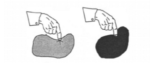
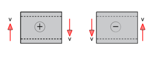
Shear force or shearing forces can be defined as a force that acts on a body/material (commonly seen in beam designs) where the force acts in one direction, and an internal force acts in the opposite direction.
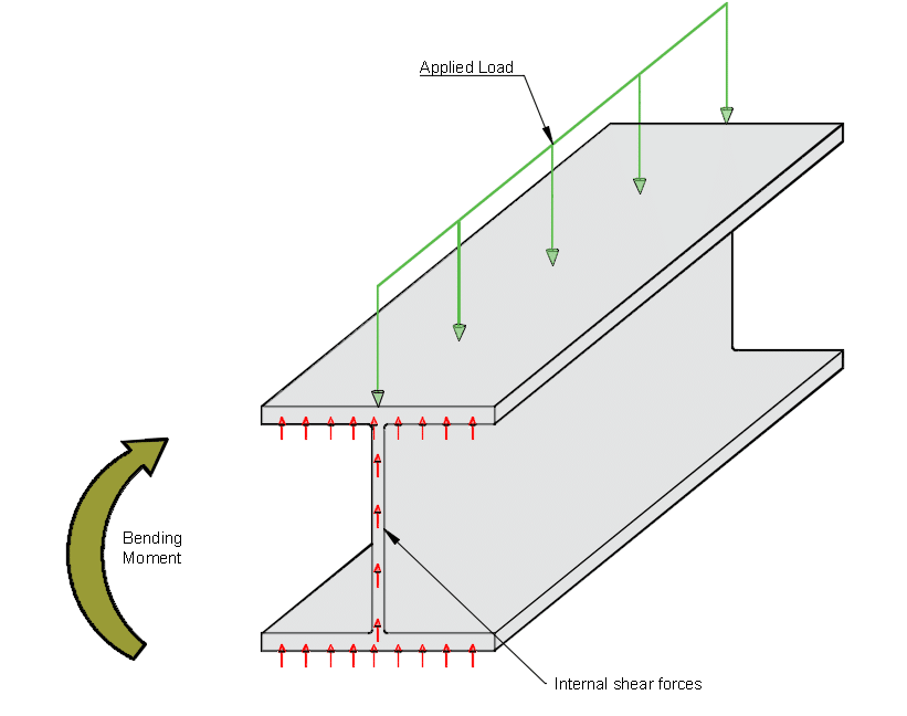
This resultant internal force keeps the beam/body in equilibrium (i.e, applied force on beam is equal to the internal shear forces in the beam). The diagram below shows how the applied force is in the downward direction, and the resultant internal forces are acting in the opposite direction (shear acting upwards).
When we design steel, concrete, timber or any material which is subjected to a load, shear force will always need to be checked against the shear capacity or shear stress capacity of the section. For example, when a I-beam is loaded, the resultant shear acting on the beam needs to be checked against the resistance provided from it’s cross section.
Shear force is usually denoted as V or Ved and the units are in kilonewtons (kN), Newtons (N) or pounds (Ibf) in engineering calculations. The shear force formula depends on the support conditions of a beam (i.e. is it pinned, fixed, or multiple supports) and position of the load on the beam.
The shear capacity of a steel I-beam is determined by its cross sectional area (loaded as seen in image below) and the material properties (i.e, grade of steel, Young’s Modulus of steel).
Shear force in beams and shear force diagrams
When we analyse beams that are subjected to loads (point loads or uniformly distributed loads), we need to first consider its boundary/support conditions.
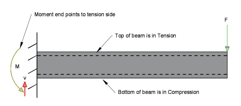
The example below is a cantilever beam with applied point load at the top. The beam support/boundary condition is fixed at the end (provides resistance to shear and bending forces).
Note – in bending moment diagrams, the moment diagram starts on the tension side (i.e. for a cantilever beam, moment diagram is above the beam – shown on tension side).
In a cantilever like the one shown below, the shear force equation is V = F.
An example design of a cantilever beam can be found in this link, which goes over the shear and bending design checks.
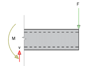
The external forces resisting the beam are shown in the diagram above, where the moment and shear are resisting the applied force at the support (note – always important to define support conditions). We can take a cut of the section to check the internal reactions.
Sign Conventions
Shear force – We can determine the sign of the section after we make a cut (see image above). If the force causes a clockwise direction (force acting downwards on the right), it is positive. If the force causes a counter-clockwise direction (force acting upwards on the right), it is negative.
Shear force diagrams
The calculated shear and bending moments of a beam are almost always shown graphically as a diagram. So it important to know how to draw bending moment and shear force diagrams as an engineer, as you will likely to be asked if you apply for a mechanical or structural engineering role.
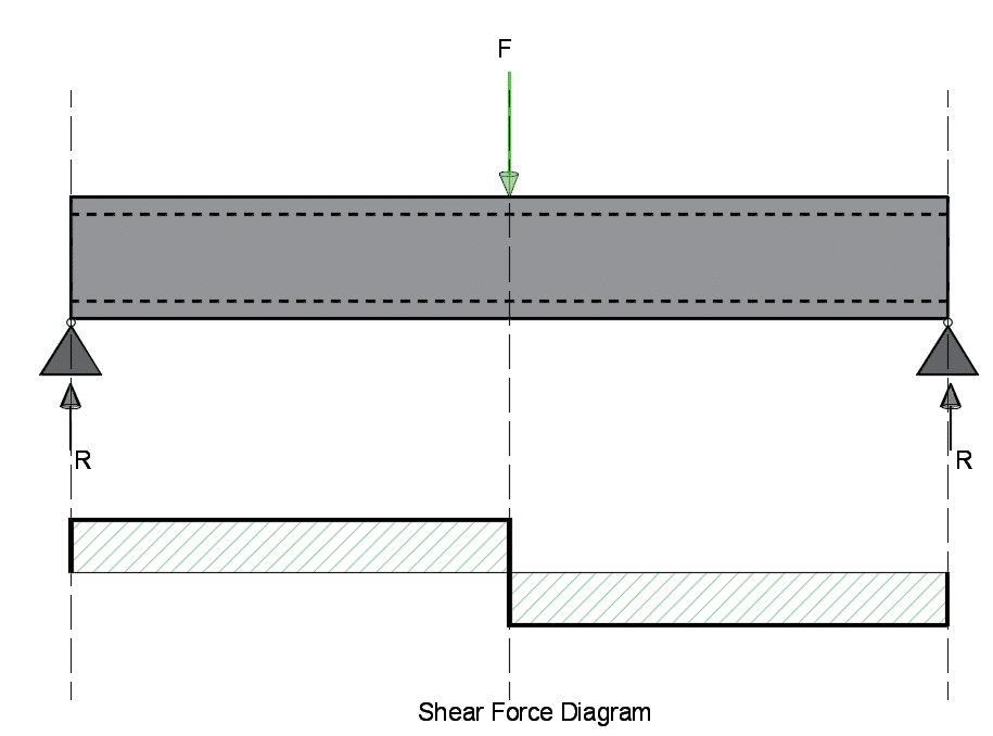
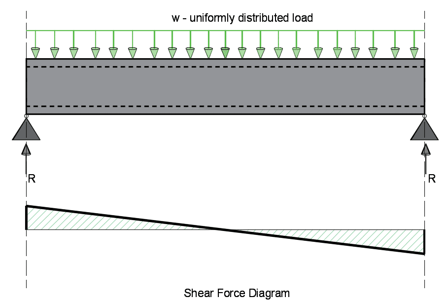
The diagrams below are typical beam loadings with a point load and uniformly distributed loads.
For understanding bending moments and bending moment diagrams, refer to this page.
Key points for Shear Diagrams:
- Before drawing out any diagrams, check boundary conditions and define the direction of the reaction loads.
- Point loads on beams cause a sharp drop in the diagram as shown in the image above.
- Where there is no load applied (see image on left above) the shear is flat/horizontal.
- UDL (Uniformly Distributed Loads) are shown on graphs as a slope (see image on the right).
- If we look at the diagram on the left, the reaction load causes the shear force to increases by a magnitude of R, before falling down by a magnitude of F, and remaining horizontal until the reaction load at the end of the beam takes it back to zero.
- Looking at the diagram on the right, the shear force increases by a magnitude of R, and then steadily decreases along the beam (slope) caused by the applied UDL, before rising again at the end of the beam due to the reaction.