Understanding Bending Moment
Table of Contents
What is a bending moment?
The bending moment is a reaction in a structural element that is subjected to an external force or moment, causing bending. Beams are a structural element, which are associated with bending moment diagrams and analysis.
When a load is applied to the beam which is large in magnitude, failure of the beam can occur. If the applied stress is greater than the ultimate tensile strength (or yield stress), failure may occur.
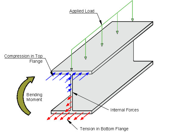
When a beam is loaded, internal reactions forces (normal forces – orientated in the beam direction) develop within the cross-section of the beam. The internal forces/reactions to the load are resolved into a resultant couple, and this must be balanced by an internal couple which is called the “bending moment”.
The internal normal forces (see sketch below) indicate compression along the top flange and tension in the bottom flange. The magnitude of each force lowers as it reaches the centroid of the I-beam, before changing signs (compression to tension).
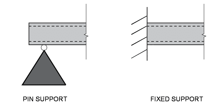
In practical terms, bending moment occur when a force is applied at a distance away from a reference point (Force x distance). It is a force which causes something to bend, and depending on how an object is fixed or supported affect the magnitude and shape of the bending moment diagram.

However, there are different failure mechanism for beams, as we need to consider the shear force and combined effects of shear and bending.
Depending on the country that you are designing your beam or structural elements in, there will be a national code that requires you undertake certain checks and keep the design within their limits.
How do supports affect bending moment diagram?

Hogging and Sagging Moments in a Beam
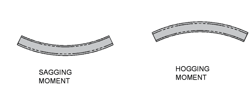
A sagging moment in a beam refers to when a beam is bending due to applied forces applied along its top flange. This results in compression in its top fibers and tension in its bottom fibers.
A hogging moment in a beam refers to when a beam is bending due to applied forces applied along its bottom flange. This results in tension in its top fibers and compression in its bottom fibers.

Example 1: Fixed Beam in Bending
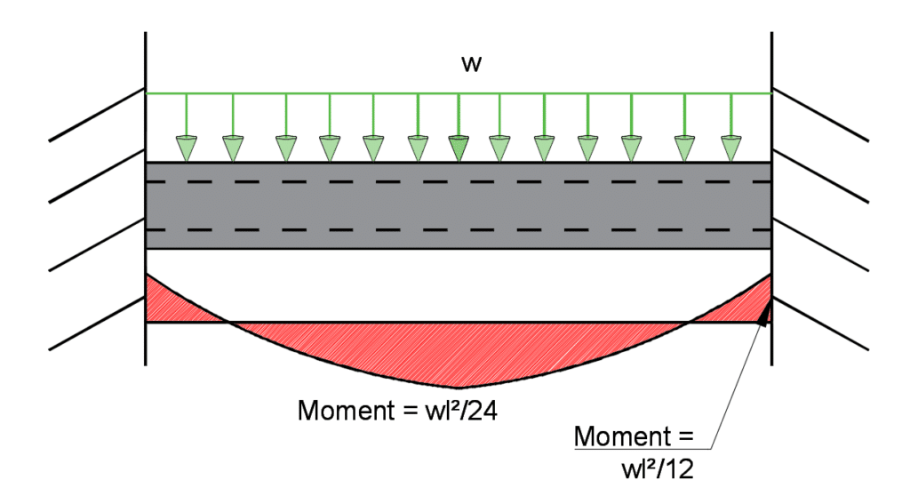
A 10m long steel beam is loaded by an applied force of 10 kN/m. The beam ends are fixed support. Calculate the bending moment at the fixed support and center of the beam.
We know that moment at the supports are : wl2/12
and the moment at the center of the beam is: wl2/24</>
Therefore, 10 x 102/12 = 83.3 kNm
Therefore, 10 x 102/24 = 41.67 kNm

