Design Examples to BS EN 1993-1-1
Table of Contents
How to design a steel beam
This article will go over typical design examples of non-composite steel beams in accordance to Eurocode 3 and its National Annexes.
The typical loadings on a steel beam are the floor deck (concrete, composite slab etc.), finishes (raised floor access, screed, carpets) and variable loads (Category of loading in accordance to Eurocode 1) .
It is common to design beams as simply supported elements in steel frame buildings, considering that it is not a moment frame and the stability is achieved through the a shear core or steel bracing. Pin supports do not transfer any moment to the frame and the moment at the ends are always zero.
When designing any beam element, it is always important to consider the bending moment diagram and understanding which side is the tension side of the beam.
For example, the diagram below indicates the tension on the bottom flange of the steel member. However, the top flange (compression) can be restrained (usually by floor), which will affect it’s moment capacity when carrying out bending checks. However, in moment frames, the bending moment is reversed at the ends and the bottom flange becomes unrestrained. This is important to note as this will affect calculations.
Typical Beam Sizes and Spans
When starting the design of any structural members, there are rules of thumb (span to depth ratio) which are commonly used to determine the size of a members which provide a starting point in a design before refining it through calculations and checks.
When steel beams depths become large/long spans, deflection will govern the design.
| Floor Type | Span (m) | |
|---|---|---|
| Composite beam & in-situ composite slab | 6-12 | |
| Steel beam & precast slab | 6-9 | |
| Slimfor beam & precast slab | 6-12 | |
| Composite beams with web openings | 6-12 | |
| Castellated/Cellular beams | 6-12 | |
| Truss | 6-12 | |
| Composite plate girder | 6-12 | |
| Element | Depth | |
|---|---|---|
| Non-composite primary beams | Floor = span/20 | |
| Roof = span/25 | ||
| Non-composite secondary beams | Floor = span/25 | |
| Roof = span/30 | ||
| Composite beams |
| |
Example 1 : Steel beam design under UDL loads. (Secondary Beams)
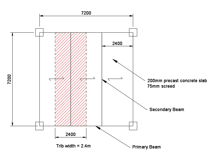
Determine adequate beam sizes for floor with a typical grid of 7.2m x 7.2m. The floor slab is a 200mm thick precast concrete slab spanning between secondary beams with 75mm screed finish and 0.5 kN/m2 for ceiling and services. The beams are fully restrained by the concrete slab. The floor is to be designed for office floor loading.
The secondary beams will need to be designed, and once the reactions are obtained, the primary beams can then be designed.

Loading Analysis
The tables above for the typical section sizes and spans for a non-composite beam indicate the following:
Non-composite secondary beam = span/25 = 288mm depth.
The Tata steel book contains typical steelwork sections that are used in the United Kingdom. There are no beams that are a depth of 288mm, so we will choose the size which is higher.
We will check a UB 305 x 165 x 51. The 165 represents the width of the flange (165mm flange) and precast planks often require a minimum bearing of 50mm – 75mm. Constructability/tolerances are important in any design.
Loading
200mm slab = 0.2 x 25 = 5 kN/m2
75mm screed = 0.075 x 22 = 1.65 kN/m2
c+s = 0.5 kN/m2
Self-weight of beam = 0.51 kN/m
Total Permanent = 7.15 kN/m2
Variable = 3.0 kN/m2
Tributary width = 2.4 m
Gk (Permanent) = 7.15 x 2.4 = 17.16 kN/m (round up to 17.7 kN/m and include self-weight of beam)
Qk (Variable) = 3.0 x 2.4 = 7.2 kN/m (round up to 7.5 kN/m)

Design Bending Moment
Design action FED = \((\gamma_G g_k + \gamma_Q q _k)\) x span
= (1.35 x 17.7 + 1.5 x 7.5) x 7.2 = 253 kN
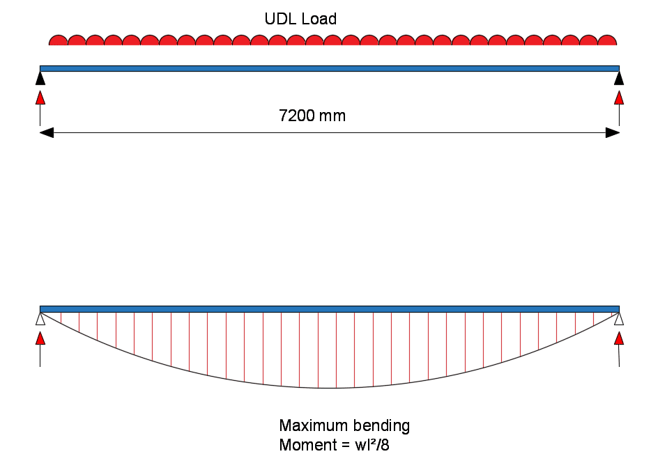
Design Bending moment, (MED) = \(\frac{F_{ED}l}{8} = \frac{253 x 7.2}{8} = 226 kNm\)
SLS Reaction Force = = (17.7 + 7.5) x 7.2/2 = 91 kN
Note – bending moment for a simply supported beam is wL2 /8.
Strength Classification
Flange thickness, tf = 13.7mm, steel grade S355. From table 3.1 of BS EN 1993-1-1,
Section Classification
Part subject to compression:
\(\epsilon\) = (235/fy)0.5 = (235/355)0.5 = 0.81
c/tf =70.6/13.7=5.15<9ε=9×0.81=7.29
C = (b-tw – 2r)/2 = (166.9 – 7.9 – 2 x 8.9)/2 = 141.2/2 =70.6 mm
Part subject to bending:
c in the equation below = the height of the web
c/t_w =265.2/7.9=33.6<72ε=72×0.81=58.32
Therefore, from Table 5.2 of Eurocode 3, section UB 305x165x54 is class 1.
Resistance of cross section
Bending moment
Since the beam section belongs to class 1, the plastic moment of resistance can be calculated from the equation below:
Mpl,Rd = Wpl,yfy/ γMO = 846 x 103 x 355 / 1.0
= 300330000Nmm
= 300.33 kNm > 226 kNm .. OKAY in bending
Shear
Design shear force is defined as VED, is
VED = FED/2 = 253/ 2 = 126.5 kN
For class 1 section design plastic shear resistance, Vpl,Rd is given in the equation below:
Vpl,Rd =Av(fy/√3)/γMO
Where Av = A-2btf + (tw + 2r)tf ≥ηhwtw
ηhwtw = 1.0 x (306.6 – 2×11.8) x 6.7 = 1896.1mm2
= 68.8 x 10² – 2 x 166.9 x 13.7 + (7.9 + 2 x 8.9)13.7 = 2659 mm2 …. OKAY
Hence, Vpl,Rd = 2659 (355/√3)1.0
= 544987 N = 545 kN > 125.6 kN
Bending and Shear
In accordance to EC3, the plastic moment resistance of the section is reduced when the applied design shear is greater than half of the design shear resistance.
VED > 0.5 Vpl,Rd
VED = 0 at mid span (bending moment is maximum at this point)
Hence, no check is required
Deflection
Deflection for simply supported beam can be calculated by the equation below:
δ = 5wL4/384EI
Total deflection = 5 x (17.7+7.5) x (7.2×103)4/384 x 210 x 103 x 11700 x 104 = 35.9mm
Deflection limit for both permanent and variable is span/200 = 7200/200 = 36mm > 35.9mm … OKAY
Variable deflection = 5 x (7.5) x (7.2×103)4/384 x 210 x 103 x 11700 x 104 = 10.68mm
Deflection limit for both permanent and variable is span/360 = 7200/360 = 20.00mm > 10.68mm … OKAY
The utilisation for the total deflection is almost 100%, and we should increase the section size to a UB 356×171.
Example 2 : Steel beam design under Point loads. (Primary Beams)
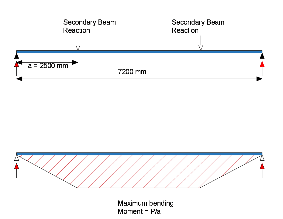
There are 2 point loads that will load the primary beams from the secondary beams.
The reactions from example 1 will be used in this design.
Loading Analysis
The tables above for the typical section sizes and spans for a non-composite steel beam indicate the following:
Non-composite primary beam = span/20 = 360mm depth.
The Tata steel book contains typical steelwork sections that are used in the United Kingdom. There are no beams that are a depth of 360mm, so we will choose the size which is higher.
We will check a UB 406 x 178 x 67. The 178 represents the width of the flange (178mm flange) and precast planks often require a minimum bearing of 50mm – 75mm. Constructability/tolerances are important in any design.
Loading
SLS permanent reactions:
Total = 91 kN
SLS Variable reaction = 7.5 x 7.2/2 = 27 kN
ULS permanent reactions:
Total = 126.5 kN

Design Bending Moment
Design Bending moment, (MED) =P x a = 126.5 x 2.5 = 316.25 kNm
Note – bending moment for 2 point loads on a simply supported beam is Pa.
Strength Classification
Flange thickness, tf = 14.3mm, steel grade S355. From table 3.1 of BS EN 1993-1-1,
Section Classification
All the thicknesses, areas, plastic modulus and second moment of areas used in the design of steel beams can be found online in the tatasteel blue book.
Part subject to compression:
\(\epsilon\) = (235/fy)0.5 = (235/355)0.5 = 0.81
c/tf =74.8/14.3=5.23<9ε=9×0.81=7.29
C = (b-tw – 2r)/2 = (178.8 – 8.8 – 2 x 10.2)/2 = 149.6/2 =74.8 mm
Part subject to bending:
c in the equation below = the height of the web
c/t_w =360.4/8.8=40.9<72ε=72×0.81=58.32
Therefore, from Table 5.2 of Eurocode 3, section UB 406x178x67 is class 1.
Resistance of cross section
Bending moment
Since the beam section belongs to class 1, the plastic moment of resistance can be calculated from the equation below:
Mpl,Rd = Wpl,yfy/ γMO = 1350 x 103 x 355 / 1.0
= 479250000Nmm
= 479.25 kNm > 316.25 kNm .. OKAY in bending
Shear
Design shear force is defined as VED, is
VED = FED/2 = (126.5 x 2)/ 2 = 126.5 kN
For class 1 section design plastic shear resistance, Vpl,Rd is given in the equation below:
Vpl,Rd =Av(fy/√3)/γMO
Where Av = A-2btf + (tw + 2r)tf ≥ηhwtw
ηhwtw = 1.0 x (409.4 – 2×14.3) x 8.8 = 3351 mm2
hw= h – 2 x tf
Av = 85.5 x 10² – 2 x 178.8 x 14.3 + (8.8 + 2 x 10.2)14.3 = 3854 mm2 …. OKAY
Hence, Vpl,Rd = 3854 (355/√3)1.0
= 789914 N = 789.9 kN > 126.5 kN
Bending and Shear
In accordance to EC3, the plastic moment resistance of the section is reduced when the applied design shear is greater than half of the design shear resistance.
VED > 0.5 Vpl,Rd
VED = 0 at mid span (bending moment is maximum at this point)
Hence, no check is required
Deflection
Deflection for simply supported beam can be calculated by the equation below:
δ = 23PL3/684EI
Total deflection = 23 x (91×103) x (7.2×103)3/684 x 210 x 103 x 24300 x 104 = 22.4mm
Deflection limit for both permanent and variable is span/200 = 7200/200 = 36mm > 22.4mm … OKAY
Variable deflection = 23 x (27×103) x (7.2×103)3/684 x 210 x 103 x 24300 x 104 = 6.64mm
Deflection limit for both permanent and variable is span/360 = 7200/360 = 20.00mm > 6.64mm … OKAY
The primary beam is adequate.
