Shear Design of Concrete Beam
Table of Contents
Shear Design of Concrete Beam - Shear reinforcement Design
This example goes through the shear design of a simply supported concrete beam in accordance to Eurocode 2, and is a very common and easy hand calculation that can be undertaken.
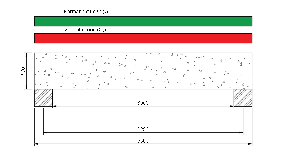
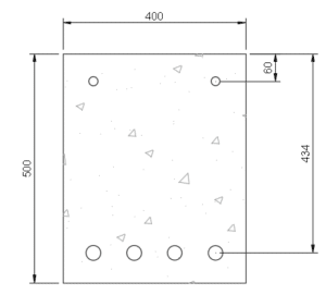
Beam shown below is a simply supported beam, where span is taken as 7000mm. The characteristic strengths of the concrete and steel are fck = 32 N/mm2. Effective depth, d=550mm and breadth = 400mm.
Permanent load, gk = 50 kN/m (including self weight)
Variable load, qk = 35 kN/m


Ultimate loading and maximum shear
Ultimate load, wu = (1.35gk + 1.5qk) kN/m
= (1.35 x 50 + 1.5 x 35) = 120 kN/m
therefore,
maximum design shear V = wu x effective span/2 = 120 x 7.0/2 = 420 kN
Design shear at face of support VED = 420 – 120×0.15 = 402 kN
Maximum shear at face of support,
Crushing strength VRd,max of diagonal strut, assuming angle ϑ = 22°, cot ϑ = 2.5
VRd,max = 0.124 bw d (1-fck /250) fck
= 0.124 x 400 x 550 (1-32/250) x 32 x 10-3
= 761 kN (> 402 kN)
Therefore, angle ϑ = 22°, cot ϑ = 2.5 will be taken.
Shear Links
The required shear links in a beam is defined the the equation below:
Asw/s = Ved/0.78dfykcotθ = 402 x 103 / (0.78 x 550 x 500 x 2.5) = 0.75
Referring to the shear reinforcement table (click on link). We can calculate the link spacing and size.
Provide 2 Legs 10mm shear links at 200mm spacing = 0.785 … OKAY
Minimum Shear Links
Asw,min/s = 0.08fck0.5bw/fyk = 0.08 x 320.5 x 400 / (500) = 0.36
We have already provided 10mm links at 200mm spacing (0.785) which is adequate.
The shear resistance of the links can be calculated below:
Vmin = Asw/s x 0.78dfykcotθ = 0.785 x 0.78 x 550 x 500 x 2.5 x 10-3 = 420 kN
Guidance Notes - General sizing
Asw = the cross-sectional area of two legs of the stirrup
S = the spacing of the legs
Z = the lever arm between the upper and lower chord members
Fywd = the design yield strength of the stirrup/link
Fyk = the characteristic strength of the stirrup reinforcement
VEd = the shear force due to the actions at the ultimate limit state
Vwd = the shear force in the stirrup
VRd,s = the shear resistance of the stirrups
VRd,max = the maximum design value of the shear which can be resisted by the concrete strut
Maximum longitudinal spacing between shear links = 0.75 d
Maximum transverse spacing between legs in a series of shear links = 0.75 d (≤600mm)
Main steel reinforcement bars should be within a 150mm distance to a shear leg (i.e, check the min distance between bottom/top bar to shear leg)
