Pad Foundation Design Example to EC2
Table of Contents
What are Pad Foundations?
Pad foundations are a type of shallow foundations, which support low loaded buildings (houses, 2-3 storey buildings). It transfers the load from the building into the underlying soil.
Pad foundation designs are based on the load acting on the pad, and also depends on the bearing capacity of soil. The foundation can either be reinforced or non-reinforced, but this depends on the magnitude of the load.
The pad itself can be rectangular or square and the thickness of the pad should be deep enough allowing the transfer of force into the ground. The plan area of the foundation is dependent on the load and bearing capacity of the soil.
The depth of a pad foundations are typically between 600mm – 2000mm but once the pad becomes too deep, it may not be economical anymore, and it may be better to use pile foundations. This is especially the case for foundations where the competent ground strata is too deep for the pad foundation to reach.
Types of pad foundation failure can be for the following reasons:
- Bearing failure (load on footing causes large movement of soul on a shear failure surface).
- Structural failure (Pad foundations crack and fail under bending, shear due to large loads)
- Overturning and Sliding (applied moment and horizontal force is larger than the restoring moment and sliding resistance of the pad).
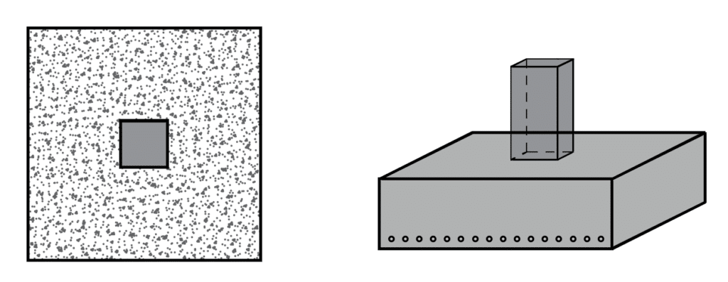
Types of Pad Foundations
Reinforced Pad Foundations – These are foundations containing reinforcement bars for tension and compression in the foundation. The bars used in the design are typically grade 500B in accordance to British Standards, but this means the yield stress of the bar is 500 N/mm2.
Concrete pad foundation – These are foundations that are just mass filled concrete bases, containing no reinforcement. This is usually for supports undertaking a minimal amount of load. (It is always better to put the minimum amount of reinforcement to avoid any cracking).
Combined Pad Foundations – These foundations occur when the pads are too close together due to closely spaced columns. This involves making a larger pad foundation supporting 2 or more columns.
Ground beams and Pad foundations – This involves using ground beams at the foundation level to transfer load into the pads. This can be practically seen in housing construction where we have ground beams supporting masonry walls.
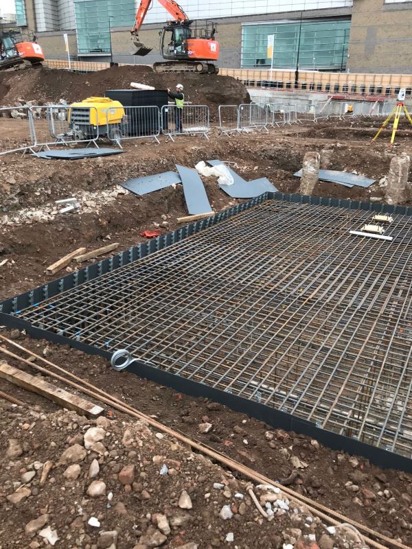
Structural Pad Foundation Design Example - Eurocode 2
Pad Foundation Design Example using prescriptive method
The structural pad foundation is to be designed against a Permanent load of 1200 kN and Imposed load of 550 kN. There is a moment of 250 kNm (permanent) and 200 kNm (imposed).
The column size is 450 x 450mm.
fck = 40 N/mm2
fyk = 500 N/mm2
Max bearing stress = 200 N/mm2
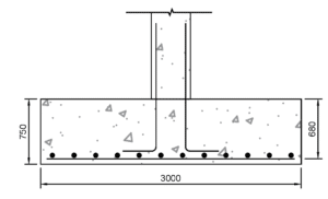
Determine size of pad at serviceability limit state
Base weight is 3.75m x 3.75m x 0.75 x 25 = 265 kN
Total SLS Load = 1200 + 550 +265 = 2015 kN
Minimum pad area = 2015/200 = 10.1m2
Add an additional 25% for moment = 10.1 x 1.25 = 12.63m2
The area of the pad = 3.75 x 3.75 = 14.06m2
Calculate eccentricity
e = M/P = (250 + 200)/2015 = 0.22m
For no tension:
6 x 0.22 = 1.32m > L , okay
depth of base = 0.75m
Bearing Stresses at SLS
pmax = P/A + My/I
pmax = 2015/14.06 + 450 x (3.75/2)/(3.75 x 3.753/12)
pmax = 143.3 + 51.2 = 194.5 kN/m2
pmax = 143.3 ± 51.2 = 194.5 and 92.1 kN/m2
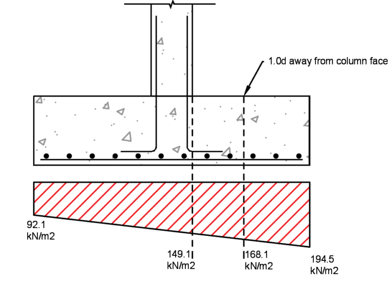
Ultimate Limit state - soil bearing pressure
Note – do not include self-weight
Column design axial load:
ULS Vertical Load = 1.35 x (1200) + 1.5 x 550 = 2445 kN
M = 1.35 x 250 + 1.5 x 200 = 640 kNm
p = 2445/14.06 + 640 x (3.75/2)/(3.75 x 3.753/12)
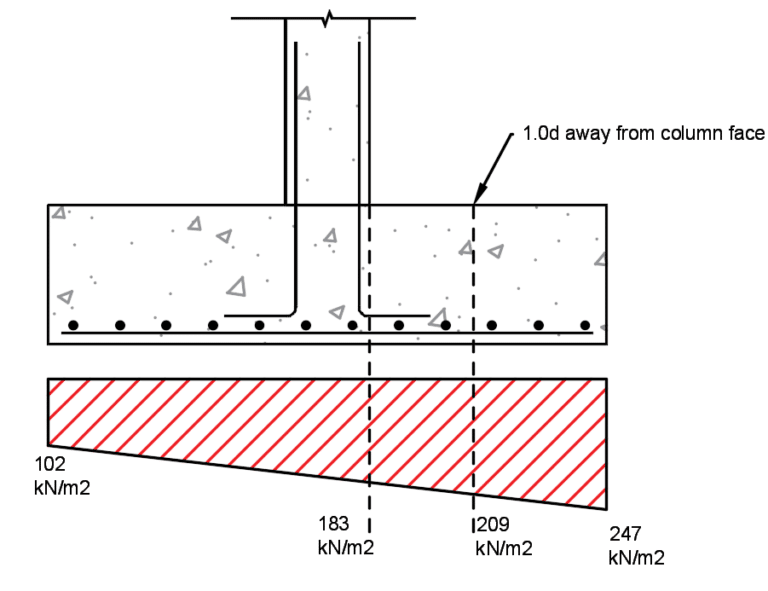
pmax = 174 ± 72.82 = 246.71 and 101.18 kN/m2
Maximum shear resistance of foundation
The depth of the foundation is 750mm and the effective depth to reinforcement has been assumed to be 680mm.
At the column face, \(V_{rd,max}\)
= \( 0.5ud [0.6(1- \frac{f_{ck}}{250} )] \frac{f_{ck}}{1.5} \)
= \(0.5(4\times450) \times 680 \times [0.6(1-\frac{f_{40}}{250} )] \frac{40}{1.5} \)
= 8225 kN (> 2445 kN)
Punching Shear
Punching shear is a failure mechanism in slabs and foundations, which causes shear stresses to develop at a perimeter of 2.0d from the edge of the column face. A more detailed explanation can be found on this page – What is punching shear?
Basic control perimeter = column perimeter + 4πd
= 4 x 450 + 4π x 680 = 10345 mm
Area within perimeter = (450 + 4d)2 – (4-π)(2.0d)2
= (450 + 1800)2 – (4-π)(1360)2 = 3.47 x 106 mm
therefore,
Punching shear force, \(V_{Ed}\) = (2445 – (3.47 x (247+102)/2)) = 1840 kN
Punching shear stress \(v_{Ed} = \frac{V_{Ed}}{Perimeter \times d}\)
\(v_{Ed} = \frac{1840 \times 10^3}{10345 \times 680} = 0.262 N/mm^2\)
Bending Reinforcement
Maximum bending at the face of the column is defined by the equation below:
\(M_{u} = (183 \times 1.65^2 \times 0.5) + (247-102)\times 1.65^2/3\)
Distance to face of column is 3.75/2 – 0.45/2 = 1.65m
=381 kNm per m width
For the concrete
\(M_{u}/bd^2f_{ck} = 381 \times 10^6/(1000 \times 680^2 \times 40) = 0.0206\)
From the lever-arm curve, la can be determine or z = d[0.5 + √(0.25-K/1.134)]
\(z = 680[0.5 +\sqrt 0.25 – 0.0206/1.134] = 667mm\), check if this is less than 0.95d (0.95 x 680 = 646 mm)
use z = 646 mm
\(A_s = \frac{M}{0.87f_{yk}z}\) = (381x 10^6)/(0.87 x 500 x 646) = 1356 mm2/m
Therefore, provide B20 bars @ 200mm c/c, As = 1570 mm2/m.
Check Bar Stresses:
Stress in reinforcement can be checked through the equation below:
\(\sigma_s = \frac{f_{yk}}{\gamma_{ms}} \frac{\psi_2 Q_k + G_k}{1.5Q_k + 1.35 G_k} \frac{A_{s,req}}{A_{s,prov}} \frac{1}{\delta}\)
where \(\psi_2\) can be taken from the table NA.A1.1, which contains values for buildings.
\(\delta\) can be taken as 1.0
\(\frac{f_{ck}}{\gamma_{ms}}\) = 435 for 500 MPa reinforcement.
Stress in reinforcement can be checked through the equation below:
\(\sigma_s = 435 \frac{0.7 \times 550 + 1200}{1.5 \times 550+ 1.35 \times 1200} \frac{1356}{1570} = 243 MPa\)
We can check the 243 MPa on the allowable stresses for bars. The maximum bar spacing can be taken as 175mm.
We have chosen a bar spacing of 200mm, which is greater than 175mm.
Increase the spacing of the bars to 175mm c/c. Therefore, new area of steel is 1795mm2/m.
The table for maximum bar stresses can be found in this page: One way slab design to EC2
Final Punching Shear
The resistance of the concrete shear needs to be checked with the reinforcement added to the concrete.
We need to determine the percentage of steel in the section.
\(\frac{A_s}{bd} = \frac{1570}{1000\times 680} = 0.0022 (=0.23% < 2%\)
\(v_{rd,c} = [0.12k \times (100 \times \rho \times f_{ck})^{1/3}] \)
where \(K = 1+ \sqrt{200/d}\)
where \(K = 1 + \sqrt{200/680} = 1.54\)
\(v_{rd,c} = [0.12 \times 1.54 \times (100 \times 0.0023 \times 40)^{1/3}] = 0.39 N/mm^2 \)
\(V_{rdc} = v_{rdc} u_1 d = 0.39 \times 10345 \times 680 \times 10^{-3} = 2746 kN\)
\(2746 kN (> V_{Ed} = 1840 kN)\)
Minimum Shear Force @ 1.0d from column
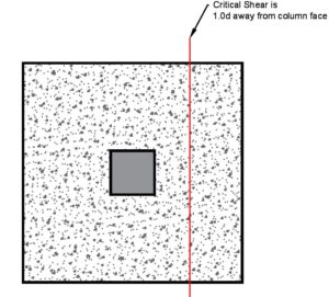
At the critical section for shear, normal shear at 1.0d from the column face.
VEd at 1.0d is 209 kN/m per m width
Design shear force, VEd = 209 x 103 / (1000 x 680) = 0.31 N/mm2
From the previous calculation, we determined the shear stress resistance, vrd,c to be 0.39 N/mm2 > 0.31 N/mm2 …. OKAY
Summary of Pad Foundation design
In summary, the following checks are needed in the structural design of any pad foundation.
- Determine load take – down (Vertical, horizontal and moments)
- Size the plan dimensions using SLS loads against known soil bearing capacity (Note – soil can not take tension)
- Determine ULS bearing pressure
- Calculate maximum shear resistance of foundation at the column face
- Calculate applied punching shear stress in foundation
- Determine required bending steel in the foundation
- Do a final check on punching shear resistance
- Check normal shear at 1.0d away from column face

This Post Has One Comment
Thank you so much