Understanding BS EN 1991-1-4
Table of Contents
How to Design for Wind Loads
Wind loads in the UK are calculated in accordance to Eurocode 1 – 1- 4 (Eurocode 1: Actions on structures – Part 1-4: General actions – wind actions) and its relevant national annex.
This Eurocode and national annex contain information and equations which are used to derive the wind pressure acting on a structure as well as its relevant force coefficients. These forces are then used in the structural analysis of a building and are often checked for stability (i.e. is the building going to overturn?).
Wind loading is an important factor in any design, especially when checking for stability. High excessive wind loads in a building could result in tension piles (expensive) in a piled foundation and require large cores/shear walls to distribute the load evenly through the building.
Swaying of the building is important as the occupants would not want to feel this kind of motion in high rise buildings. Columns are always designed for sway limits and checked whether they are slender or short.
The specific Eurocode for wind actions are listed below:
- BS EN 1991-1-4
- NA to BS EN 1991-1-4
The content list in BS EN 1991-1-4 are the following:
- General
- Design situations
- Modelling of Wind actions
- Wind velocity and velocity pressure
- Wind actions
- Structural factor cscd
- Pressure and force coefficient
- Wind actions on bridges
- Annexes
The main aspects to wind loading design when looking a building are calculating the peak wind velocity factor (see examples below) and applying the correct factors acting on a wall or roof (monopitch, duo-pitch, etc) and designing the beams/structural elements for uplift/minor axis bending and more checks in general.
Key Wind Loading Equations to Eurocodes
Altitude factor
calt = (10/z)0.2Aalt + 1, where Aalt is the altitude of the site and can be found in the on altitude checker.
Fundamental basic wind velocity
vb,0 = vb,map x calt
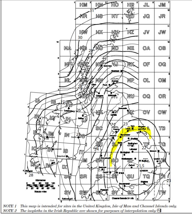
where, vb,map is found on a map containing the wind velocities for different cities (Figure NA.1).
Direction factor
Direction factor is denoted by Cdir is based on table NA.1 of the National Annex. This is usually taken as 1.0 (conservative design)
Season Factor
Season factor is taken from NA.2 and is usually taken as 1.0 for a conservative measure.
Season factor; cseason = 1.00
Basic wind velocity (Exp. 4.1); vb = 0.613 x (cdir x cseason x vb,0)2
Orography factor is denoted by co
This factor is not always significant and can be taken co = 1.0
Check terrain category : is it in the country side or town
Peak Velocity Pressure
The peak velocity factor is in country terrain is, qb(z)=Ce(z) qb
The peak velocity factor is in town terrain is, qb(z)=Ce(z). Ce(T). qb
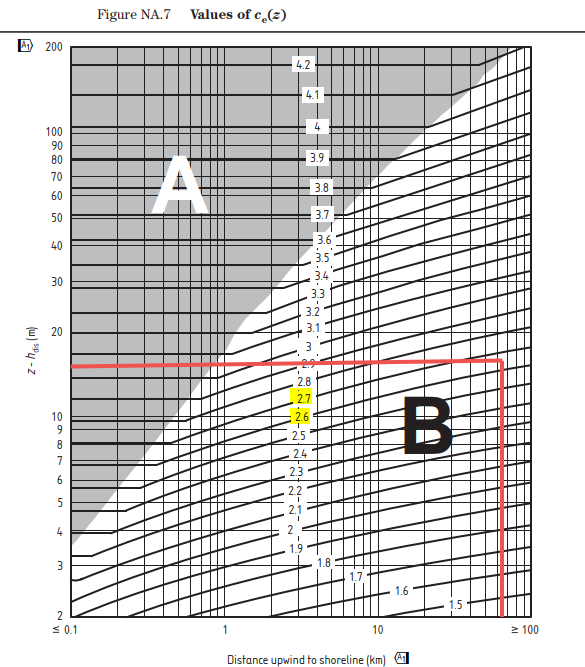
Ce(z) is a value that can be found in figure NA.7, which is determined by distance upwind to the shoreline (km).
Ce(T) is a value that can be found in figure NA.8, for town terrain but can be taken as 1.0 for a conservative peak velocity.
Values of external pressure coefficients for vertical walls of rectangular-plan buildings
Values of external pressure coefficients for vertical walls of rectangular-plan buildings (Cpe,10) and (Cpe,1)
Cpe,10 are values for loaded areas 1m2
Cpe,1are values for loaded areas greater than 1m2 which is much more commonly used in design of larger buildings
| h/d | Zone | ||||
|---|---|---|---|---|---|
| A | B | C | D | E | |
| 5 | -1.2 | -0.8 | -0.5 | +0.8 | -0.7 |
| 1 | -1.2 | -0.8 | -0.5 | +0.8 | -0.5 |
| \(\leq\) 0.25 | -1.2 | -0.8 | -0.5 | +0.7 | -0.3 |
Wind Loading Design Example
This is a design example to calculate the peak wind velocity acting on a structure.
The building is located in the countryside, around 55km from the sea and assumed to be 45m above sea level.
Width of building on plan = 50m
Length of building on plan = 85m
Height of the building is 15m

Wind speed velocity (FigureNA.1 of BS EN 1991-1-4); vb,map = 22.5 m/s
Distance to shore; Lshore = 55 km
Altitude above sea level; Aalt = 45.0m
Altitude factor
calt = (10/z)0.2Aalt x 0.001m + 1
calt = (10/15)0.245 x 0.001m + 1 = 1.04
Fundamental basic wind velocity; vb,0 = vb,map x calt = 23.6 m/s
Fundamental basic wind velocity; vb,0 = 22.5 x 1.04 = 23.4 m/s

Cdir is based on table NA.1 of the National Annex.
Note 4 of the table determines that the direction factor may be taken as 1.0 for a conservative value.
Direction factor; cdir = 1.00
Season factor; cseason = 1.00
Basic wind velocity (Exp. 4.1); vb = 0.613 x (cdir x cseason x vb,0)2 = 336 N/m2
vb = 0.613 x (1.0 x 1.0 x 23.4)2 = 336 N/m2
Orography factor not significant; co = 1.0
Terrain category; Countryside
Determine Ce(z) from figure NA.7
Hdist = 0, therefore z – Hdist = 15m
Reading off the graph below indicates a value between 2.6 and 2.7, therefore, this gives a figure of Ce(z) = 2.65.
qp = 2.65 x 336 = 890 N/m2 (0.89 kN/m2)

Wind Load Eurocode Example 2
This is a design example to calculate the peak wind velocity acting on a structure.
The building is located in the town, around 100km from the sea and assumed to be 25m above sea level. Assume wind speed velocity as 23.5 m/s
Width of building on plan = 20m
Length of building on plan = 30m
Height of the building is 32m
Wind speed velocity (FigureNA.1 of BS EN 1991-1-4); vb,map = 23.5 m/s
Distance to shore; Lshore = 100 km
Altitude above sea level; Aalt = 25m
Altitude factor (Refer to equation NA.2b of National Annex to BS EN 1991-1-4)
calt = (10/z)0.2Aalt x 0.001m + 1 = 1.02
calt = (10/32)0.225 x 0.001m + 1 = 1.02
Fundamental basic wind velocity; vb,0 = vb,map x calt = 24 m/s
Fundamental basic wind velocity; vb,0 = 23.5 x 1.02 = 24 m/s
Cdir is based on table NA.1 of the National Annex.
Direction factor; cdir = 1.00
Season factor; cseason = 1.00
Basic wind velocity (Exp. 4.1); vb = 0.613 x (cdir x cseason x vb,0)2 = 353 N/m2
vb = 0.613 x (1.0 x 1.0 x 24)2 = 353 N/m2
Terrain category; Town
Take Ce(T) as a value of 1.0
Determine Ce(z) from figure NA.7
Hdist = 0, therefore z – Hdist = 32m
Reading off the graph indicates a value of 3.1, therefore, this gives a figure of Ce(z) = 3.1.
qp = 3.1 x 353 = 1094 N/m2 (1.094 kN/m2)
