Decoding BS EN 1992-1-1
Table of Contents
Steps to Concrete Beam Design to EC2
- Determine Loading
- Determine Support Conditions
- Check Required Reinforcement for bending
- Check Reinforcement for shear
- Check span-effective Depth Ratio
Design Example 1: Simply Supported Beam (Compression and Tension Steel)
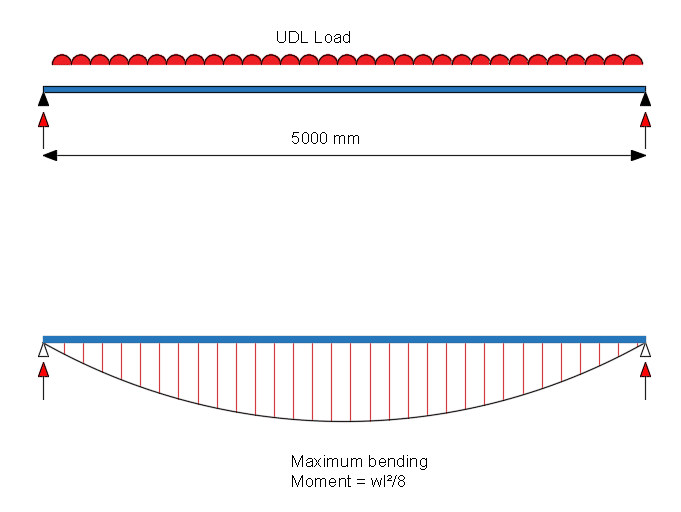
A simply supported beam is to be designed, where the span is taken as 5000mm. The characteristic strengths of the concrete is fck = 32 N/mm2. The yield strength of steel reinforcement is 500 N/mm2 . The concrete beam support bearing is 150mm.
The beam section is 400mm x 400m.
Cover to reinforcement to be 30mm. Assume tension bar to be 20mm diameter and 8mm link.
Effective depth, d= 400 – 30 – 8 -20/2 = 352mm and breadth = 300mm.
Permanent load, gk = 40 kN/m (including self weight)
Variable load, qk = 30 kN/m
The concrete beam design for this example is shown in the steps below:
Loading
Ultimate load, wu = (1.35gk + 1.5qk) kN/m
= (1.35 x 40 + 1.5 x 30) = 100 kN/m
therefore
maximum design moment M = \(\frac{w_uL^2}{8} = \frac{100\times 5.0^2}{8} = 313 kNm\)

Reinforcement for Bending and Compression
\(K=\frac{M}{bd^2f_{ck}} = \frac{313 \times 10^6}{400×352^2 \times 32}= 0.198 >K_{bal} = 0.167\) . Therefore, compression reinforcement, A’s is required.
x = 0.45d = 0.45 x 352 = 158.4mm
d’/x = (30+8+10)/158.4 = 0.30 < 0.38, therefore fsc = 0.87 fyk.
Compression steel:
\(A’_s\frac{M-0.167f_{ck}bd^2}{f_{sc}(d-d’)}\)
\(=\frac{313 \times 10^6 -0.167 \times 32 \times 400 \times 352^2}{0.87 \times 500(352-48)} = 364 mm^2\)
Provide 4B20 bars, A’s = 1256 mm2.
Tension steel, \(A_s=\frac{0.167f_{ck}bd^2}{0.87f_{yk}z_{bal}} + A_s’\)
where, from the lever arm curve, la = 0.82.
Thus,
\(A_s = \frac{0.167\times 32 \times 400 \times 352^2}{0.87\times 500 \times (0.82 \times 352)} + 364\)
\(= 2110 + 364 =2474mm^2\).
Provide 4 B32 bars, area = 3217 mm2.
Note – Keep the same number of bars top and bottom, to allow ease of fixing of rebar/cages on site (i.e. don’t use 3 bars top and 4 bars at the bottom). Also, the top bars need be a minimum of 2 bar sizes lower than the bottom bars, which is why we used B20 bars for the top reinforcement instead of using a B12 or B16.
Span- Effective Depth Ratio
\(\rho = 100A_{s,req}/bd = (100\times 2474)/(400\times 352) = 1.75%\)
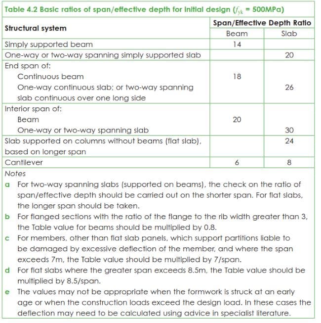
From span-ratio table, basic span/effective depth for a simply supported beam is 14.
Modification for ratio = 14 x (3217/2474) = 18.20
Span-effective depth ratio provided = 5000/352 = 14.2.
14.2<18.20 .. Therefore, it is okay.

Shear Link in Beam Design
Design for Shear
Maximum design shear V = wu x effective span/2 = 100 x 5.0/2 = 250 kN
Design shear at face of support VED = 250 – 100×0.15 = 235 kN
Maximum shear at face of support,
Crushing strength VRd,max of diagonal strut, assuming angle ϑ = 22°, cot ϑ = 2.5
VRd,max = 0.124 bw d (1-fck /250) fck
= 0.124 x 400 x 400 (1-32/250) x 32 x 10-3
= 554 kN (> 235 kN)
Therefore, angle ϑ = 22°, cot ϑ = 2.5 will be taken.
Shear Links
The required shear links in a beam is defined the the equation below:
Asw/s = Ved/0.78dfykcotθ = 235 x 103 / (0.78 x 400 x 500 x 2.5) = 0.60
Referring to the shear reinforcement table (click on link). We can calculate the link spacing and size.
Provide 2 Legs 8mm shear links at 150mm spacing = 0.671 … OKAY
Minimum Shear Links
Asw,min/s = 0.08fck0.5bw/fyk = 0.08 x 320.5 x 400 / (500) = 0.36
We have already provided 8mm links at 150mm spacing (0.671) which is adequate.
The shear resistance of the links can be calculated below:
Vmin = Asw/s x 0.78dfykcotθ = 0.671 x 0.78 x 550 x 500 x 2.5 x 10-3 = 360 kN
General Notes for shear link sizing
Asw = the cross-sectional area of two legs of the stirrup
S = the spacing of the legs
Z = the lever arm between the upper and lower chord members
Fywd = the design yield strength of the stirrup/link
Fyk = the characteristic strength of the stirrup reinforcement
VEd = the shear force due to the actions at the ultimate limit state
Vwd = the shear force in the stirrup
VRd,s = the shear resistance of the stirrups
VRd,max = the maximum design value of the shear which can be resisted by the concrete strut
Maximum longitudinal spacing between shear links = 0.75 d
Maximum transverse spacing between legs in a series of shear links = 0.75 d (≤600mm)
Main steel reinforcement bars should be within a 150mm distance to a shear leg (i.e, check the min distance between bottom/top bar to shear leg)
Design Example 2: Simply Supported Beam (Tension only)
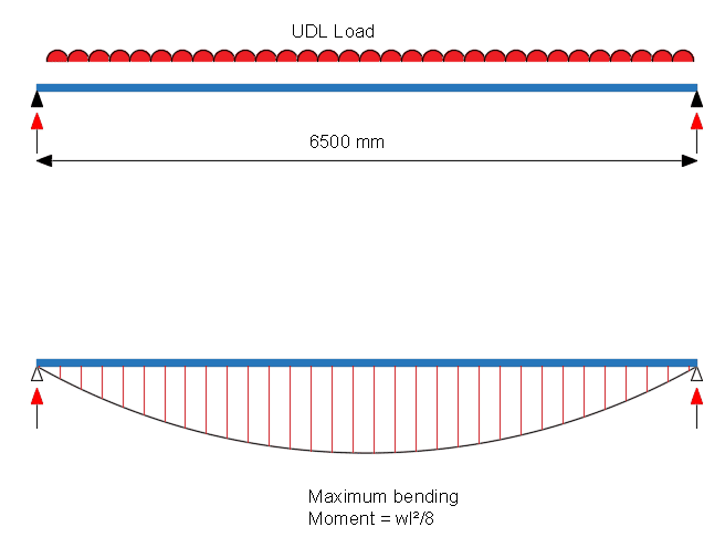
A simply supported beam is to be designed, where the span is taken as 6500mm. The characteristic strengths of the concrete is fck = 32 N/mm2. The yield strength of steel reinforcement is 500 N/mm2 . The concrete beam support bearing is 150mm.
The beam section is 400mm x 600m.
Cover to reinforcement to be 30mm. Assume tension bar to be 25mm diameter and 8mm link.
Effective depth, d= 650 – 30 – 8 -25/2 = 600mm and breadth = 400mm.
Permanent load, gk = 50 kN/m (including self weight)
Variable load, qk = 35 kN/m
The concrete beam design for this example is shown in the steps below:
Loading
Ultimate load, wu = (1.35gk + 1.5qk) kN/m
= (1.35 x 50 + 1.5 x 35) = 120 kN/m
therefore
maximum design moment M = \(\frac{w_uL^2}{8} = \frac{120\times 6.50^2}{8} = 635 kNm\)

Reinforcement for Bending
\(K=\frac{M}{bd^2f_{ck}} = \frac{635 \times 10^6}{400x 600^2 \times 32}= 0.137 <K_{bal} = 0.167\) . Therefore, compression reinforcement, is not required.
Tension steel, \(A_s=\frac{M}{0.87f_{yk}z}\)
z = d[0.5 + \(sqrt\)(0.25 – K/1.134)
z = 600 x [0.5 + \(sqrt\)(0.25 – 0.137/1.134) = 515 mm
Thus,
\(A_s = \frac{635 x 10^6}{0.87\times 500 \times (515)}\)
\(=2834mm^2\).
Provide 4 B32 bars, area = 3217 mm2.
Note – Although compression bars are not required, top bars are still needed to form the reinforcement cage
Span- Effective Depth Ratio
\(\rho = 100A_{s,req}/bd = (100\times 2834)/(400\times 600) = 1.18%\)
From span-ratio table, basic span/effective depth for a simply supported beam is 14.
Modification for ratio = 14 x (3217/2834) = 15.9
Span-effective depth ratio provided = 6500/600= 10.83.
10.83<15.9 .. Therefore, it is okay.

Shear Link in Beam Design
Design for Shear
Maximum design shear V = wu x effective span/2 = 120x 6.50/2 = 390 kN
Design shear at face of support VED = 390 – 120 x 0.15 = 372 kN
Maximum shear at face of support,
Crushing strength VRd,max of diagonal strut, assuming angle ϑ = 22°, cot ϑ = 2.5
VRd,max = 0.124 bw d (1-fck /250) fck
= 0.124 x 400 x 650 (1-32/250) x 32 x 10-3
= 900kN (> 372kN)
Therefore, angle ϑ = 22°, cot ϑ = 2.5 will be taken.
Shear Links
The required shear links in a beam is defined the the equation below:
Asw/s = Ved/0.78dfykcotθ = 390 x 103 / (0.78 x 400 x 500 x 2.5) = 1.0
Referring to the shear reinforcement table (click on link). We can calculate the link spacing and size.
Provide 2 Legs 10mm shear links at 125mm spacing = 1.256 … OKAY
Minimum Shear Links
Asw,min/s = 0.08fck0.5bw/fyk = 0.08 x 320.5 x 400 / (500) = 0.36
We have already provided 10mm links at 125mm spacing (1.256) which is adequate.
The shear resistance of the links can be calculated below:
Vmin = Asw/s x 0.78dfykcotθ = 1.256 x 0.78 x 650 x 500 x 2.5 x 10-3 = 796 kN
Design Example 3: Cantilever Beam (Tension only)
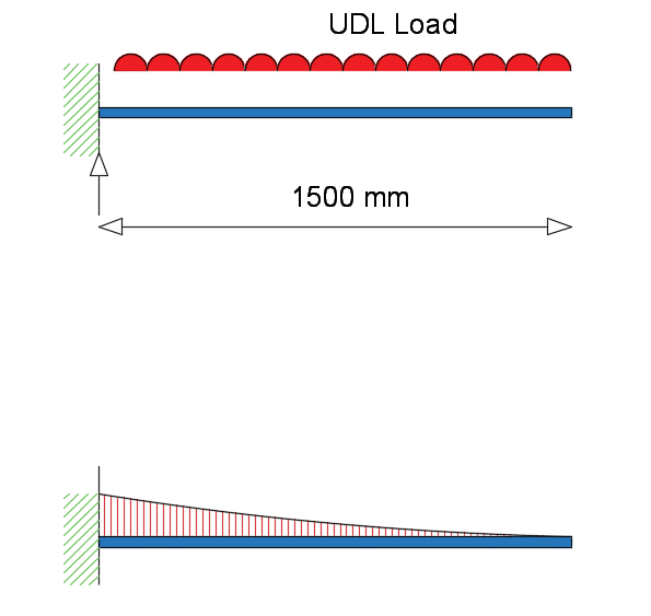
A cantilever beam is to be designed, where the span is taken as 1500mm. The characteristic strengths of the concrete is fck = 32 N/mm2. The yield strength of steel reinforcement is 500 N/mm2 . The concrete beam support bearing is 150mm.
The beam section is 400mm x 600m.
Cover to reinforcement to be 30mm. Assume tension bar to be 25mm diameter and 10mm link.
Effective depth, d= 650 – 30 – 10 -25/2 = 598 mm and breadth = 400mm.
Permanent load, gk = 50 kN/m (including self weight)
Variable load, qk = 35 kN/m
The concrete beam design for this example is shown in the steps below:
Loading
Ultimate load, wu = (1.35gk + 1.5qk) kN/m
= (1.35 x 50 + 1.5 x 35) = 120 kN/m
therefore
maximum design moment M = \(\frac{w_uL^2}{2} = \frac{120\times 1.5^2}{2} = 135 kNm\)

Reinforcement for Bending
\(K=\frac{M}{bd^2f_{ck}} = \frac{135\times 10^6}{400x 598^2 \times 32}= 0.03 <K_{bal} = 0.167\) . Therefore, compression reinforcement, is not required.
Tension steel, \(A_s=\frac{M}{0.87f_{yk}z}\)
z = d[0.5 + \(sqrt\)(0.25 – K/1.134)
z = 598x [0.5 + \(sqrt\)(0.25 – 0.03/1.134) = 582 mm
Limit for z = 0.95d = 0.95 x 598 = 568mm (use 568mm for z)
Thus,
\(A_s = \frac{135x 10^6}{0.87\times 500 \times (568)}\)
\(=550mm^2\).
Provide 4 B16 bars, area = 804 mm2.
Note – Tension bar is on the top flange of the concrete beam (see bending moment diagram)
Span- Effective Depth Ratio
\(\rho = 100A_{s,req}/bd = (100\times 550)/(400\times 598) = 0.23%\)
From span-ratio table, basic span/effective depth for a cantilever beam is 6.
Modification for ratio = 6x (804/550) = 8.77
Span-effective depth ratio provided = 1500/598= 2.5.
2.5<8.77.. Therefore, it is okay.

Shear Link in Beam Design
Design for Shear
Maximum design shear V = wu x effective span = 120x 1.5 = 180 kN
Crushing strength VRd,max of diagonal strut, assuming angle ϑ = 22°, cot ϑ = 2.5
VRd,max = 0.124 bw d (1-fck /250) fck
= 0.124 x 400 x 650 (1-32/250) x 32 x 10-3
= 900kN (> 180kN)
Therefore, angle ϑ = 22°, cot ϑ = 2.5 will be taken.
Shear Links
The required shear links in a beam is defined the the equation below:
Asw/s = Ved/0.78dfykcotθ = 180 x 103 / (0.78 x 400 x 500 x 2.5) = 0.5
Referring to the shear reinforcement table (click on link). We can calculate the link spacing and size.
Provide 2 Legs 10mm shear links at 250 mm spacing = 0.628… OKAY
Minimum Shear Links
Asw,min/s = 0.08fck0.5bw/fyk = 0.08 x 320.5 x 400 / (500) = 0.36
We have already provided 10mm links at 250mm spacing (0.628) which is adequate.
The shear resistance of the links can be calculated below:
Vmin = Asw/s x 0.78dfykcotθ = 0.628 x 0.78 x 650 x 500 x 2.5 x 10-3 = 400 kN
